
 EN
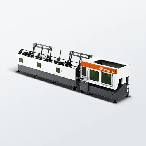
Achieving Precision Cuts to Minimize Material Waste
Root Causes: Kerf inconsistency and dimensional drift in high-volume runs
During long production runs, even a stable laser cutting machine can lose edge consistency. Kerf—the width of material removed by the beam—varies due to nozzle degradation, focus shift, or thermal expansion of the gantry and workpiece. Fluctuations in sheet thickness or surface condition further compound this: identical settings may yield wider or narrower cuts across a single nest. Dimensional drift accumulates rapidly—a 0.05 mm shift per edge can translate into unacceptable deviation across hundreds of parts. Because downstream bending or assembly relies on repeatable geometry, unmonitored drift leads directly to scrap, rework, and avoidable material waste. Effective root cause tracking therefore compares first-part and mid-run measurements—not just final part dimensions—to isolate when and where consistency breaks down. The issue is not the laser source alone, but the dynamic interplay of heat, motion, and cut path over time.
Technical Levers: Beam quality, dynamic focus control, and thermal stability
Precision hinges on controlling beam delivery—not just power output. A high-quality beam with low M² produces a smaller, more stable focused spot, minimizing kerf variation across both thin and thick stock. Dynamic focus control maintains optimal focal height as the cutting head traverses contours, preventing edge taper and width drift. Thermal stability is equally critical: cooled optics, rigid machine frames, and temperature-compensated encoders all mitigate geometry shifts during continuous operation. Many leading shops integrate these levers with real-time kerf width and edge quality monitoring, enabling automatic correction before waste accumulates—especially valuable when switching between metal grades or thicknesses. ISO 9013:2017 provides an authoritative framework for classifying cut quality, helping teams define objective limits for perpendicularity, roughness, and striation.
Optimizing Laser Cutting Machine Speed for Throughput and Consistency
Bottleneck Drivers: Parameter recalibration delays and material-change downtime
Throughput losses rarely stem from raw beam speed. Instead, the largest bottlenecks occur during transitions—particularly manual recalibration after each material change. Adjusting focal offset, power, frequency, and assist gas pressure can consume several minutes per setup. In high-mix environments, such recalibrations may absorb 15–25% of available cutting time. Worse, operators sometimes skip test cuts to recover lost time—introducing dimensional drift and inconsistent kerf width. Manual loading and suboptimal nesting create additional idle gaps, while every stop disrupts thermal equilibrium, making early sheets after restart prone to variability. Stored parameter libraries—validated against actual material batches—directly reduce this overhead and stabilize output consistency.
Performance Enablers: Assist gas tuning, pulse modulation, and intelligent feed-rate profiling
Sustained speed requires matching process variables to how the material responds—not applying blanket settings. Assist gas tuning is foundational: higher pressure clears molten metal efficiently on thin sheets, while lower, stabilized pressure prevents turbulence and dross in thicker plate. Pulse modulation reduces localized heat input at corners and fine features, enabling faster travel without burning or slag formation. Intelligent feed-rate profiling adjusts cutting speed in real time based on curvature, kerf width, and local thermal load—preventing stalls at sharp corners and preserving a stable cutting front. With these controls, thin sheet speeds routinely reach 15–20 m/min, while 3–6 mm plate operates reliably at 1–5 m/min—improving both throughput and edge consistency across extended runs.
Selecting the Right Laser Cutting Machine for Material Compatibility
Material compatibility is the first filter when choosing a laser cutting machine. If the wavelength, power, and cutting head are mismatched to the metal, even flawless CAD paths produce wasted parts.
High-Reflectivity Challenges: Copper, brass, and aluminum back-reflection risks
Copper, brass, and aluminum reflect much of the incident beam—up to 90% for aluminum and even more for copper until surface melting begins. This back-reflection risks overheating collimators, damaging protective lenses, and triggering system shutdowns. Leading manufacturers address this with real-time back-reflection monitoring, optical path isolation, and advanced cutting modes like spiral or wobble. Before purchasing, verify the machine’s rated capacity for reflective alloys—not just mild steel. A unit rated for 20 mm mild steel may only handle 10–15 mm aluminum and 5–10 mm copper. Without built-in safeguards, the process becomes unstable and maintenance costs rise significantly.
Fiber vs. CO₂ Lasers: Absorption efficiency, cut quality, and operational cost trade-offs
Fiber lasers operate near 1 µm, where metals absorb energy far more efficiently than at the 10.6 µm CO₂ wavelength. This translates to faster piercing, superior thin-sheet performance, and lower electrical consumption. While CO₂ lasers still deliver smoother edges on some thick nonmetals and select stainless applications, they demand more frequent maintenance and precise beam alignment. For shops focused primarily on metals, fiber lasers typically deliver lower cost-per-part through reduced energy use, faster cycle times, and higher uptime. However, for operations regularly cutting thick stainless or nonmetal composites, a CO₂ system may justify its higher complexity. The right choice depends on your actual material mix—not nominal wattage.
Ensuring Clean, Post-Processing–Free Cuts with Process Control
Common Defects: Dross adhesion and excessive heat-affected zone in thick stainless steel
In thick stainless steel, dross adhesion and excessive heat-affected zone (HAZ) often trace back to unstable thermal delivery. When assist gas purity falls below 99.95%, oxide droplets re-solidify on the bottom edge instead of being ejected cleanly. Slow cutting speeds compound the problem by adding excess heat to the kerf—widening the HAZ and producing discolored, brittle edges. Field audits show that stabilizing beam focus and gas pressure alone can reduce dross incidence by roughly 30% in previously uncontrolled runs. Left unchecked, these defects drive secondary grinding—raising per-part cost and extending cycle time, especially in batch production.
Control Parameters: Nozzle geometry, gas purity, pressure sequencing, and standoff optimization
Clean, post-processing–free cuts depend on four tightly coordinated parameters. Nozzle geometry governs gas flow symmetry; a worn or misaligned tip introduces turbulence that pulls molten metal back into the kerf. Gas purity prevents oxidation—nitrogen at ≥99.99% preserves bright, oxide-free edges on stainless steel, while oxygen blends accelerate cutting but risk dross if pressure ramps too quickly. Pressure sequencing must begin low during piercing and increase only after full penetration to avoid blowout or incomplete melt ejection. Standoff optimization maintains consistent focal position across sheet undulation—typically within ±0.5 mm. Together, these controls stabilize kerf dynamics and dramatically reduce manual cleanup on thick sections.
Frequently Asked Questions (FAQ)
What is kerf in laser cutting?
Kerf refers to the width of material removed by the laser beam during the cutting process. Consistent kerf width is crucial for precision cuts, as any deviation can lead to dimensional inaccuracies and material waste.
How can I minimize material waste during long production runs?
Minimizing waste involves monitoring kerf consistency, optimizing beam quality, maintaining thermal stability, and tracking measurements throughout the production run to identify when consistency issues arise.
What's the difference between fiber and CO₂ lasers?
Fiber lasers are more efficient for cutting metals due to better energy absorption, lower electrical costs, and faster processing times. CO₂ lasers are better suited for certain thick nonmetals and stainless steel applications but require more maintenance.
How do I ensure clean cuts without post-processing?
Ensuring clean cuts requires controlling nozzle geometry, using high-purity assist gases, optimizing pressure sequencing, and maintaining focus to prevent defects such as dross adhesion and heat-affected zones.