
 EN
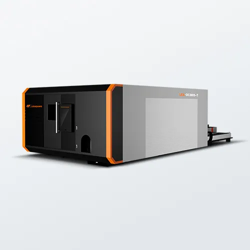
Cutting Quality Defects in Tube and Plate Laser Cutting Machines
Defects on cut edges of a tube and plate laser cutting machine usually signal one of three root causes: nozzle condition, focal position, or assist gas delivery. Technicians should inspect these before changing speed or power.
Burrs, dross, and rough edges: diagnosing nozzle wear, focal shift, and assist gas inconsistencies
Diagnose dross and burrs by checking nozzle condition first. A worn or contaminated nozzle distorts gas flow and leaves molten material on the bottom edge. Replace the nozzle when the orifice shows visible ovality or spatter buildup. Next, verify focus position. Thermal lensing and lens shift move the focal point away from the material surface—too low or too high a focus produces rough edges and increases dross. Use a beam alignment tool to confirm focus after warm-up. Assist gas inconsistencies also cause burrs: oxygen cuts carbon steel quickly but can create heavy oxidation; nitrogen delivers cleaner edges on stainless steel but demands stable pressure. Inspect regulators, filters, and hoses for leaks or moisture—fluctuating pressure creates intermittent dross bands. Record gas purity and flow for each material lot, and adjust nozzle standoff and gas pressure incrementally. A 2024 audit of metal fabrication lines found that 38% of rough-edge defects traced back to unstable assist gas delivery. Work from the nozzle outward: check nozzle, focus, and gas. This order isolates the most frequent causes before altering power or speed. Operators often raise power to remove burrs, but that masks the true fault. Instead, return to baseline settings and change one variable at a time—this method keeps edge quality repeatable across tube and plate jobs.
Striations, drag lines, and oxidation: optimizing gas type, pressure stability, and thermal focus for tubes and plates
Striations on thin-wall tube and plate edges often arise from gas selection and thermal focus drift. Use nitrogen for stainless and aluminum to limit oxidation; use oxygen for thick carbon steel when speed matters—but accept mild oxidation as a trade-off. Pressure stability matters more than peak pressure: a 2024 process study found that pressure variation above ±0.1 bar doubled drag-line depth. Install a buffer tank or larger regulator close to the cutting head, and check the gas line for restrictions. Thermal focus drift occurs as the cutting head heats during long runs—the focal length shifts slightly, changing kerf shape and drag-line spacing. Use a temperature-compensated collimator or allow full machine warm-up before production. Set focal position per wall thickness: thin tube walls need focus near the top surface; thick plate requires deeper focus inside the material. Record optimal focus settings per material and thickness to reduce trial cuts. Oxidation on the top edge can be limited by balancing assist gas flow and cutting speed—slow speeds allow heat buildup and oxide formation, while excessively fast speeds may not fully eject molten metal. Regular cleaning of the protective lens also prevents thermal focus drift.
Precision Loss and Path Deviation in Multi-Axis Tube and Plate Laser Cutting Machines
Precision loss in a tube and plate laser cutting machine often begins with mechanical holding and motion errors. The issues below separate clamping-related path drift from beam and parameter drift.
Clamping instability and rotational slippage during tube cutting
Tubes and profiles are never perfectly straight. Small-diameter tubes deflect more during rotation, making it harder to maintain opening positions relative to other features. If chuck center height, jaw alignment, or clamping force is inconsistent, the tube rotates eccentrically—causing wobble, rotational slippage, and path deviation. Use follow-up supports to reduce tube whip, and apply real-time centering inside each clamping segment. Laser scanning systems correct the cutting head trajectory based on measured deflection and can hold position tolerance near 0.2 mm. Mechanical probing may work, but it adds setup time and manual adjustment. Regularly inspect chuck jaws, support rollers, and pneumatic clamping pressure; clean contact surfaces and remove chips to prevent slip. Where tight tolerance is critical, separate tube advancement from laser cutting to reduce vibration.
Beam misalignment and parameter drift across complex tube and plate contours
Even stable clamping cannot prevent path deviation if the beam or motion parameters drift. Rails, rack-and-pinion sets, drives, servo response, gantry wear, and height-following systems shape the real cutting path. Backlash may be invisible on straight cuts but appears on small holes, sharp corners, arcs, and rapid direction changes. Beam-to-nozzle concentricity drift alters kerf width and cut position. Thermal focal shift from dirty optics or lens heating changes spot size. Heat input from dense contours on tubes can also move tolerances. Kerf compensation direction, lead-in placement, and pierce-point distance can create apparent misalignment. Check beam centering, lens condition, nozzle condition, gas pressure stability, and motion accuracy. Use path strategies that limit heat concentration on thin tubes and plates.
Process Instability: Piercing Failures and Dynamic Power Fluctuations
Piercing failures in a tube and plate laser cutting machine usually appear as blowouts, heavy spatter, or incomplete penetration. In many cases, the laser pierce sequence is misaligned with assist gas timing and focal position. A short pierce delay traps molten material in the kerf, causing back-spatter that damages the nozzle; a long delay wastes energy and widens the pierce hole. Operators should check three parameters before adjusting the resonator: pierce time, nozzle standoff, and peak power ramp. For thicker plate sections or round tube walls, pierce frequency and gas pressure must be tuned together to avoid thermal shock.
Dynamic power fluctuations amplify these problems. Momentary voltage sags, transients, and harmonics can reduce resonator output or servo holding torque without tripping the main breaker—resulting in an unstable pierce where the first pulse pierces, the second does not, and the third blows through. On tube and plate contours, this creates uneven kerf width and path drift, especially during rapid repositioning. Monitoring DC bus voltage and assist gas pressure during the pierce window separates electrical noise from mechanical backlash. A dedicated supply line, low-impedance grounding, and surge protection are essential for stable cutting. If the input voltage varies by more than a few percent during the pierce, fix the power path first.
Mechanical Safety Risks: Collision Avoidance and Corner Integrity in Tube Laser Cutting Machines
Mechanical safety in a tube and plate laser cutting machine depends on controlling both moving elements and thermal stress at part edges. Collision risks concentrate where the cutting head, chuck, and tailstock travel through shared space. A misloaded tube, an unflat plate, or a protruding clamp can turn a rapid traverse into a high-force impact. Leading safety audits identify rapid traverse and rotary repositioning as the highest collision-risk phases, so operators should verify material flatness, tube straightness, and fixture clearance before cycle start. Modern systems add capacitive height sensing, torque limits, and real-time collision detection to stop motion within milliseconds, preventing most tooling fractures (2023 machine safety benchmark).
Corner integrity creates a different mechanical hazard. When the beam slows into a sharp corner, dwell time and local heat input increase—producing a wider kerf, a fragile oxide edge, or micro-cracks. On tubes, a weak corner can bend or shatter during unloading; on plates, an acute corner can catch a glove or scratch downstream tooling. Program small corner loops, reduce peak power by 5–10% near sharp transitions, and use lead-out tabs so the separated part cannot fall against the nozzle or strike the chuck. These moves keep cut edges strong and reduce the chance of part ejection.
Finally, operator protection requires interlocks, light curtains, and fixed guards around loading and unloading zones. Machine guarding violations remain one of the most frequent OSHA citations in fabrication, reinforcing the need for enclosed beam paths and controlled access (OSHA 2023). Collision avoidance and corner control together protect both the operator and the machine structure from uncontrolled motion, sharp-edge injuries, and avoidable downtime.
FAQ Section
What are the common causes for cutting defects in tube and plate laser cutting machines?
Cutting defects are typically caused by nozzle wear or contamination, focal position shift, or inconsistencies in assist gas delivery. Diagnosing and addressing these areas first often resolves most issues.
How can striations and drag lines be minimized?
Using nitrogen for stainless steel and aluminum reduces oxidation, while ensuring stable assist gas pressure prevents drag lines. Additionally, maintaining thermal focus and using temperature-compensated collimators helps mitigate these defects.
What methods help prevent path deviation during multi-axis tube cutting?
Ensure clamping stability and reduce tube whip using follow-up supports. Regularly inspect chuck, support rollers, and pneumatic pressures to avoid slippage. Real-time laser scanning systems also help correct trajectory.
How can piercing failures and dynamic power fluctuations be avoided?
Check pierce time, nozzle standoff, and peak power ramp parameters before adjusting resonator settings. Additionally, monitor DC bus voltage and assist gas pressure; surge protection and stabilizing the power path help prevent dynamic power fluctuations.
What safety measures are essential when using tube laser cutting machines?
Essential measures include interlocks, light curtains, fixed guards, capacitive height sensing, and real-time collision detection. Program corner loops and use lead-out tabs to ensure operator safety and edge quality.
Table of Contents
- Cutting Quality Defects in Tube and Plate Laser Cutting Machines
- Precision Loss and Path Deviation in Multi-Axis Tube and Plate Laser Cutting Machines
- Process Instability: Piercing Failures and Dynamic Power Fluctuations
- Mechanical Safety Risks: Collision Avoidance and Corner Integrity in Tube Laser Cutting Machines
-
FAQ Section
- What are the common causes for cutting defects in tube and plate laser cutting machines?
- How can striations and drag lines be minimized?
- What methods help prevent path deviation during multi-axis tube cutting?
- How can piercing failures and dynamic power fluctuations be avoided?
- What safety measures are essential when using tube laser cutting machines?