
 EN
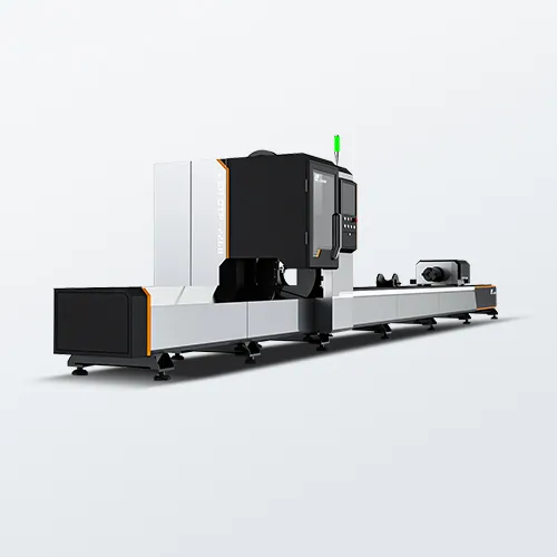
Material Compatibility and Reflectivity Requirements
Selecting the right laser cut machine for tube processing starts with matching the laser source to the metal. The two most common sources—fiber and CO₂—behave very differently on reflective and thermally conductive alloys.
Fiber vs CO₂ laser sources: Matching metal type, reflectivity, and thermal conductivity
Fiber lasers emit at approximately 1 µm wavelength, which is absorbed far more efficiently by aluminum, copper, brass, and stainless steel than the 10.6 µm CO₂ wavelength. For copper, absorption at 1 µm reaches 40–50%, compared to just 5–8% for CO₂ (Laser materials processing data 2026). This low CO₂ absorption creates two critical issues: reduced cutting speed and a high risk of back-reflections that can damage optics. High thermal conductivity—especially in copper and aluminum—pulls heat away from the cut zone rapidly. Fiber lasers counter this with high power density and a tightly focused spot, maintaining energy concentration where it’s needed. While CO₂ systems cut mild and stainless steel effectively, they require longer focal lengths and precise beam alignment for reflective tubes. Reflective metals also exhibit steep angle-dependent reflectivity, demanding tight control over beam incidence and tube rotation. For mixed production runs involving copper or aluminum, a fiber laser is the safer, more versatile baseline configuration.
Thickness limits and absorption efficiency for stainless steel, aluminum, and copper
Stainless steel absorbs fiber laser energy strongly; a 3–6 kW system typically cuts wall thicknesses from 0.5 mm to 12 mm with clean, weld-ready edges. Aluminum’s high reflectivity and thermal conductivity demand more peak power—4–10 kW fiber lasers generally handle up to 10–15 mm wall thickness, whereas CO₂ systems often struggle below 2 mm due to back-reflection risks. Copper remains the most challenging: practical fiber cutting usually maxes out around 8–12 mm wall thickness, and edge oxidation must be controlled using nitrogen or oxygen assist. Crucially, copper absorbs roughly five times more fiber energy than CO₂ energy (Laser processing data 2026), enabling faster ramp-up to cutting speed across all three metals. Still, wall thickness dictates key process parameters—including laser power, focus position, and assist gas flow. Thin-wall copper and aluminum benefit from high pulse modulation, while thicker sections require continuous-wave operation and slower feed rates to preserve edge integrity.
Laser Power, Beam Quality, and Motion Control Performance
Power–speed–focal depth trade-offs for precision mitre and contour cuts
Precision mitre and contour cuts on tube demand careful balancing of power, speed, and focal depth—especially as cut angles and wall thicknesses change across 3D profiles. Higher laser power accelerates melting and supports faster travel on a given thickness, but excessive speed relative to power causes incomplete fusion and rough bottom edges. Conversely, too much power for a given speed and focal position widens the kerf and expands the heat-affected zone, leading to burn marks or oxidation on thin-walled sections. Beam quality—measured by beam parameter product (BPP) or M²—directly influences achievable detail: lower values yield smaller focused spots and higher energy density, enabling fine mitre edges and tight contour radii. Focal depth must place the smallest spot at or slightly below the material surface to ensure consistent edge quality across complex geometries. A stable focal point prevents taper on angled entry and exit points. In practice, operators tune power and speed together—and verify focal waist placement after optical alignment—to maintain dimensional and metallurgical integrity.
CNC repeatability (±0.05 mm) and its impact on 3D tube geometry accuracy
CNC repeatability of ±0.05 mm directly determines whether nested tube parts fit together after cutting. In 3D tube geometry, small positioning errors accumulate across rotary axes, chuck clamping, and carriage travel—making tight repeatability essential for angular alignment in mitre joints and positional consistency of holes relative to profiles. Even minor deviations can create uneven root gaps at tube ends, increasing weld fit-up time and compromising joint strength. Achieving this tolerance requires a motion system with high stiffness, minimal backlash, and stable thermal behavior during extended operation. Acceleration and deceleration profiles must be tuned to prevent overshoot at sharp corners or contour transitions. Regular calibration of rotary axes and linear guides ensures sustained performance within specification. For structural tube assemblies produced in batch, buyers should request test cuts validated with CMM measurements—not rely solely on published repeatability claims.
Machine Configuration and Physical Integration Factors
Vertical vs horizontal laser cut machine layouts: Setup time, gravity distortion, and floor space
Selecting the right laser cut machine configuration requires weighing setup time, gravity-induced distortion, and available floor space. Vertical layouts hold tubes upright or at steep angles, reducing machine footprint and simplifying handling of long profiles—but inadequate clamping can allow gravity to pull thin-walled tubes out of round. Horizontal systems support the workpiece along its full length, minimizing distortion and easing loading of heavy or irregular profiles; however, their longer beds typically consume more floor area. Setup time follows a similar trade-off: vertical loaders may require hoists or precision chucks, while horizontal beds allow faster manual positioning—particularly valuable in high-mix environments where operators need visibility and access to the full profile. In contrast, vertical systems excel in continuous production of long, narrow tubes where floor space is constrained. The table below summarizes the main trade-offs.
| Layout | Setup time | Gravity distortion risk | Floor space |
|---|---|---|---|
| Vertical | Higher for heavy/long tubes; may need hoist | Higher for thin walls if support is inadequate | Smaller footprint |
| Horizontal | Lower for mixed, heavy profiles | Lower across supported length | Larger footprint |
Process Optimization for Real-World Tube Cutting Output
Nozzle design, assist gas selection (N₂, O₂, air), and pressure tuning for burr-free holes and weld-ready edges
Nozzle geometry critically influences gas flow stability and kerf width. Double-layer nozzles help suppress plasma formation when cutting aluminum. For stainless steel, nitrogen at 12–18 bar delivers clean, oxide-free, weld-ready edges. Oxygen reduces power demand on thick carbon steel but introduces oxidation requiring secondary cleaning. Compressed air at 6–10 bar offers a cost-effective balance for thin-wall tubes—provided pressure is carefully matched to diameter and wall thickness. Excessive pressure causes turbulence and dross; insufficient pressure leaves burrs. Coaxial alignment between nozzle and laser beam is non-negotiable: centering within ±0.05 mm prevents one-sided burr formation on round tubes. Standoff distance should be maintained between 0.5–1.5 mm for consistent hole edge quality. For critical weld preparations, 99.99% pure nitrogen avoids micro-oxidation. Inspect nozzle wear every shift—eroded orifices distort the gas column and degrade edge finish. Finally, pair assist gas pressure ramping with machine acceleration profiles to prevent edge burn at contour entry and exit points.
FAQs
What is the difference between fiber and CO₂ laser sources?
Fiber lasers emit at a 1 µm wavelength, allowing better absorption by metals like aluminum, copper, and brass, while CO₂ lasers emit at a 10.6 µm wavelength, which is less effective on reflective or thermally conductive materials.
What are the thickness limits for different metals when using fiber lasers?
Fiber lasers can cut stainless steel between 0.5–12 mm, aluminum up to 10–15 mm, and copper around 8–12 mm, depending on power and operational parameters.
What are the pros and cons of vertical and horizontal laser cut machine layouts?
Vertical layouts save floor space but may cause gravity-induced distortion in thin walls, whereas horizontal layouts prevent distortion and are easier to load but consume more space.
How do assist gas types and pressure affect cutting quality?
Each assist gas has its advantages: nitrogen delivers oxide-free edges, oxygen reduces power demand on carbon steel, and compressed air is cost-effective for thin materials. Proper pressure tuning is essential to avoid burrs and achieve optimal cutting results.
Why is CNC repeatability important in tube cutting?
CNC repeatability ensures precise alignment of nested tube parts, reducing weld preparation time and maintaining the strength of the joints.
Table of Contents
- Material Compatibility and Reflectivity Requirements
- Laser Power, Beam Quality, and Motion Control Performance
- Machine Configuration and Physical Integration Factors
- Process Optimization for Real-World Tube Cutting Output
-
FAQs
- What is the difference between fiber and CO₂ laser sources?
- What are the thickness limits for different metals when using fiber lasers?
- What are the pros and cons of vertical and horizontal laser cut machine layouts?
- How do assist gas types and pressure affect cutting quality?
- Why is CNC repeatability important in tube cutting?